[Edited in May 2019 to reflect latest changes in the code and build environment]
Whenever there is a substantial change in FloatHub’s functionality, we’ve been happy to mail out devices with upgraded firmware to any customers who ask. We include a return mailer so that the original device can be mailed back to us. But in some circumstances — especially for overseas users — this can take a long time (and involve surprisingly high shipping charges).
So for that reason (and to promote general transparency about how FloatHub works), we’ve pulled together this guide. It should contain all the information required to flash the latest firmware onto your FloatHub provided you follow all of the steps. Please be generous with feedback (either by email or comments below), especially if something is unclear or you run into difficulty.
Background Information
A WiFi FloatHub actually has 2 completely separate microprocessors on board. In order to flash your device with a current copy of the firmware, you will need to upgrade both processors. We will cover all of the software and hardware required to do so. A Cellular FloatHub has an additional (third) microprocessor, but that code almost never changes so flashing the cellular subsystem will not be covered in this guide.
Required Hardware
In addition to your FloatHub device and access to a computer, you’ll need one USB A-to-B Cable (like this). You should have received one with your FloatHub device, but any standard USB A-to-B Cable will do. You’ll also need a small Phillips screwdriver to open your FloatHub.
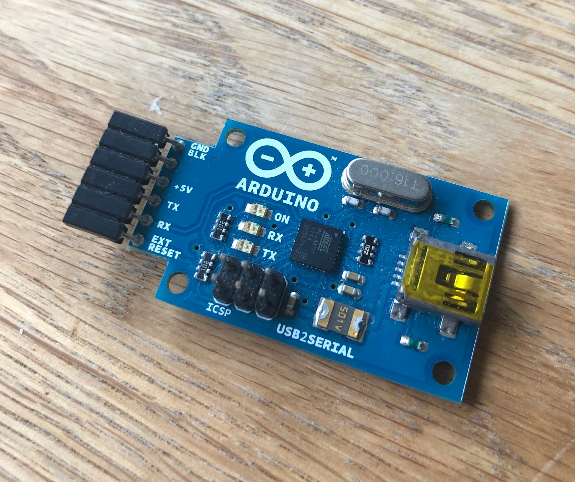
Something else you’ll need but are far less likely to have on hand is an FTDI adapter. We highly recommend this one from Adafruit:
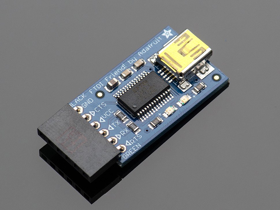
As it is exactly set up to be pin compatible with the programming header inside your FloatHub.
Required Software
To compile and flash the FloatHub code, you’ll need Version 1.8.9 of the Arduino development environment. At the time of writing this is the most recent version of the Arduino software and it is available at:
https://www.arduino.cc/en/Main/Software
Choose Windows/Mac/Linux as appropriate for your computer and operating system.
You’ll also need the actual FloatHub code which is freely available on GitHub:
https://github.com/floathub/device
You can use the “Clone or Download” button on GitHub to get a current copy of the code. There are not (currently) any release branches as we always commit tested code to the public repository that reflects the latest functionality.
Important There are two additional things you’ll need to do after you install Arduino 1.8.9:
- A stock Arduino install includes serial buffer settings which less than optimal for FloatHub. Accordingly, you should follow the directions in the README file (in the GitHub repository) to bump up the hardware and software serial buffer sizes.
- You will need to add ESP8266 support to your Arduino environment. By far the easiest way to do this is to follow the instructions at the ESP8266 repository to Install with Boards Manager. You’ll want version 2.5.1 of the ESP8266 board support for Arduino.
Step-by-Step Process
Ok, with all those prerequisites out of the way, the flashing process is actually quite straightforward. The first step is remove the four screws that hold the two halves of your FloatHub’s case together:

You’ll then want to connect the USB A-to-B Cable from your computer to your FloatHub:

Next, launch the Arduino software you set up above. You need to load (File → Open) the following file (from the FloatHub code on GitHub):
device/mega/mega.ino
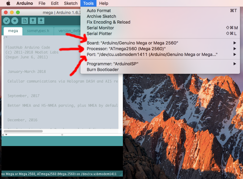
You then need to make sure the following options are set:
- Tools → Board: Arduino/Genuine Mega or Mega 2560
- Tools → Processor: ATmega2560 (Mega 2560)
- Tools → Port: {Anything that lists a Mega2560 entry}
A screenshot of all this should look something like this:
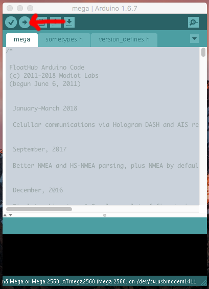
Once you have verified that all of the above is correct, you can go and and flash the code by pushing the Arduino upload button:
That’s it for the first microprocessor. You’ll want to now disconnect the USB cable, and connect the FTDI adapter to the second microprocessor, the so-called ESP8266. It should have a 6 pin 90-degree connector that the FTDI adapter will slide right onto:
You may need to bend the female connector on the FTDI board up a little in order to clear other components. The USB cable that comes with and connects to the FTDI board should then be plugged into your computer. The ESP8266 will now be powered by this USB connection. You can check if it has power by pressing the reset button. That button is immediately below the 90-degree connector, on the right. There is another push button just to the left, which is the GPIO button. If you push and release just the reset button, a couple of LEDs on the ESP8266 should flash on and then off.
Once you’ve verified you have power to the ESP8266, you need to place it in programming mode. This is done by pushing both the GPIO button and the reset button and then releasing only the reset button. The red LED on the ESP8266 should be glowing brightly red while you still have the GPIO button pressed but have released the reset button. If you then release the GPIO button, the RED LED should drop in brightness but still be glowing faintly. This dimmer red glowing indicates that the ESP8266 is in programming mode.
With the ESP8266 ready to go, you need to load the following file into the Arduino programming environment:
device/esp8266/esp8266.ino
If you are building for a cellular FloatHub device, you want to uncomment the following define on line 52:
#define CELLULAR_CODE_ON
Then make sure the following options are set:
- Tools → Board: Adafruit Feather HUZZAH ESP8266
- Tools → Flash Size: 4M (3M SPIFFS)
- Tools → lwIP Variant: v1.4 Higher Bandwidth
And the port setting under tools is whatever port your FTDI adapter is in. This can vary by operating system, but if you look at the list of port both before and after you plug in the FTDI adapter, it should be obvious which one it is.

You can then go ahead and push the upload button to flash the ESP8266. This will generally take quite a bit longer than the first flashing (via the regular USB cable).
That should be it. The device should maintain its settings (Public WiFi, FloatHub ID, Security Key, etc.), so you should be able to readily check and see that is operating correctly.